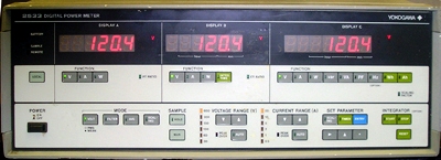
YOKOGAWA 2533-253313 CALIBRATION and YOKOGAWA 2533-253313 REPAIR

 
A calibration by Custom-Cal is performed by engineers with extensive OEM experience. We have the expertise and the necessary standards to perform the YOKOGAWA 2533-253313 Calibration, onsite calibration may be available. We specialize in quick turnaround times and we can handle expedited deliveries upon request.


   YOKOGAWA 2533-253313   Description / Specification:    
YOKOGAWA 2533-253313 3-phase 4-wire (AC) Digital Power Meter

The Yokogawa 253313 3-phase 4-wire (AC) Digital Power Meter is a solution to accurate effective power measurement of distorted waveforms. This power meter is ideal for use on production lines and in research and development. A single digital power meter can measure effective values of AC voltage from 3 to 600 V (DC voltage can be superimposed), AC current from 100 mA to 30 A, and single-phase power from 300 mW to 18 kW (600 mW to 36 kW in three-phase, three-wire systems). Voltage, current, and power measurements can be conducted by simply making a key selection. This meter features faster response time and a greater number of features than conventional models. A built-in photo coupler provides complete isolation between the power meter input and output circuits. With its high dielectric strength and high resistance to external noise, this meter offers stable and reliable operation. Specifications. Engineering Units: m, k, M, V, A, W, VA, var, Hz, h (hour). Function Selection: Manual for Display A, B, C each by front-panel keys (or remote via optional GPIB or RS-232-C interface). Sample Rate: Approx. 2.5 times/s. Ranging: Automatic or manual (or remote via optional GPIB or RS-232-C interface). Effective Measuring Range: 10 to 110% of rated value (range). Response Time: Approx. 0.4 S. (at filter OFF, for analog output within ±0.2% accuracy against an input variation from 30 to 100% of range, or from 100 to 30% of range). Display: LED display. Type of Input Voltage: Direct (CT isolation after ranging). Type of Input Current: CT isolation (secondary ranging). Rated Input (Range) Volt: 30, 60, 100, 150, 300, 600 V. Rated Input (Range) Current: 0.5, 1, 2, 5, 10, 20 A. Max. Allowable Input (for 1 s): 3.5 x range (peak) or 1,400 Vpk (whichever is less), 10 x range (peak) or 70 A pk (whichever is less). Max. Allowable Input (continuous, at 50 or 60 Hz): 2 x range (rms) or 1,000 V pk (whichever is less), 3 x range (rms) or 50 Apk (whichever is less). Options. /GP-IB, GPIB Interface. /RS232C, RS-232-C Interface. /FRQ, Frequency Measurement, Range: 10 Hz to 200 kHz (filter OFF), 2 to 500 Hz (filter ON).


Standard Calibration $805.00 *
Click on Logo for More Prices
*This is a Web introductory price for one calibration of the YOKOGAWA 2533-253313. Price does not in most cases include measurement performance data. Pricing does include NIST traceable calibration and issue of a calibration certificate and calibration label. Pricing may vary slightly due to volume and location of laboratory supporting calibration. Volume pricing may apply. On-site fees may apply depending on logistics, location and volume of work to be completed during the visit.


Related Bench Equipment Terms and Definitions. For a complete list go to our  Terms and Definitions Page.

dBc
dBc (decibels relative to the carrier) is the power ratio of a signal to a carrier signal, expressed in decibels. If the dBc figure is positive, then the relative signal strength is greater than the carrier signal strength. If the dBc figure is negative, then the relative signal strength is less than carrier signal strength.

Load Regulation
Load regulation is the capability to maintain a constant voltage (or current) level on the output channel of a power supply despite changes in the supply's load (such as a change in resistance value connected across the supply output).

Power Linearity
When changing the power level and measuring the differences (in dB) between actual and displayed power levels, the power linearity is ± half the span (in dB) between the maximum and the minimum value of all differences.

Settling Time
Settling time of an output device is the time elapsed from the application of an ideal instantaneous step input to the time at which the amplifier output has entered and remained within a specified error band, usually symmetrical about the final value.


Please contact us for your YOKOGAWA 2533-253313 CALIBRATION and/or YOKOGAWA 2533-253313 3-phase 4-wire (AC) Digital Power Meter REPAIR

I'm interested in: 
Calibration Type (Select one):
Repair Information:
 Serial Number:

 Is there any physical damage?  
 If yes, describe:


What is the description of the problem?

How/when did the problem start?


 (*) Required Fields    For formal quote please fill in all fields.
Company:
From (Email):*
Contact Name:*
Country:*
Address 1:
Address 2:
City:
State/Territory/Province: *
Zip/Postal Code:
Phone:*

Comment: