AEROFLEX-IFR 2948B CALIBRATION and AEROFLEX-IFR 2948B REPAIR

 
A calibration by Custom-Cal is performed by engineers with extensive OEM experience. We have the expertise and the necessary standards to perform the AEROFLEX-IFR 2948B Calibration, onsite calibration may be available. We specialize in quick turnaround times and we can handle expedited deliveries upon request.

Need another Communication Analyzer?
Shop for Comparable Products on our
 used Communication Analyzer page or new Communication Analyzer page

 
   AEROFLEX-IFR 2948B   Description / Specification:   Spec Sheet 
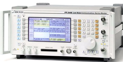
AEROFLEX-IFR 2948B Low Phase-Noise Wireless Communications Service Monitor

The Aeroflex IFR 2948B Low Phase-Noise Wireless Communications Service Monitor comes with a full performance spectrum analyzer. The performance of the 2948B enables signal-to-noise measurements of better than 46 dB to be made on receivers with 12.5 kHz channel spacing. Stored settings may be recalled from internal memory or from a memory card allowing fast and straightforward set up. The spectrum analyzer provides spans from 100 Hz per division to 100 MHz per division and also has a fully adjustable reference level. The Aeroflex 2948B will measure the power of low level signals such as those encountered when monitoring off-air signals or those found when probing a circuit. 150 Watts measurement is provided without the need for external attenuators, so high power base stations can be measured directly. Measurement accuracy of better than 10% is guaranteed all the way down to 5 mW on the N-Type connector. The signal generator provides coverage from 400 kHz to 1.05 GHz with +5 dBm output (+7 dBm overrange) and fast switching speed. Level accuracy is ±2 dB at all levels above -127 dBm. Full duplex operation is provided by the 2948B allowing testing of duplex radios as well as simultaneous testing of repeater transmit and receive paths. The 2948B provides extensive support for the various tone signaling systems used in Professional Mobile Communications such as DTMF, TONE REMOTE (Option), DCS and CTCSS. Analysis of audio signals, whether from the demodulated signal or the audio input direct, can be viewed for further inspection. The oscilloscope can either be combined with the measurement screen in the Tx, Rx or AF test modes or ‘zoomed’ to a full screen display. Options. Option 1 - 600 ohm Matching Unit. Option 2 - Analog Systems Card. Option 3 - High Stability OCXO. Option 4 - Parallel Interface. Option 5 - GPIB Interface. Option 6 - Memory Card Drive with real time clock. Option 8 - SSB Demodulator. Option 9 - Occupied Bandwidth Measurement. Option 10 - NMT Cellular. Option 11 - AMPS Cellular. Option 12 - TACS Cellular. Option 13 - MPT 1327 trunking. Option 14 - PMRTEST. Option 15 - EDACSTM Radio Test. Option 16 - EDACSTM Repeater Test. Option 18 - LTR Trunking. Option 21 - Demodulation Filters. Option 22 - POCSAG Decode. Option 23 - CCITT Filter. Option 24 - CMESS Filter. Option 26 - Tone Remote. Option 29 - Plus 2 Distortion Notch Filters board. Option 30 - Bail Arm and Front Panel Stowage Cover. Option 31 - IF Output Capability. Option 32 - Internal Battery.


Standard Calibration $955.00 *
Click on Logo for More Prices
*This is a Web introductory price for one calibration of the AEROFLEX-IFR 2948B. Price does not in most cases include measurement performance data. Pricing does include NIST traceable calibration and issue of a calibration certificate and calibration label. Pricing may vary slightly due to volume and location of laboratory supporting calibration. Volume pricing may apply. On-site fees may apply depending on logistics, location and volume of work to be completed during the visit.


Related Communication Terms and Definitions. For a complete list go to our  Terms and Definitions Page.

Extinction Ratio
Extinction ratio is the ratio of two optical power levels, of a digital signal generated by an optical source, where P1 is the optical power level generated when the light source is "on," and P0 is the power level generated when the light source is "off." The extinction ratio may be expressed as a fraction, in dB, or as a percentage. Extinction ratio = P1/P0

Receiver
A receiver is a detector and electronic circuitry to change optical signals into electrical signals.

Telecom Bands
Optical fiber communications typically operate in a wavelength region corresponding to one of the following Bands. O Band (original): 1260–1360 nm. E Band (extended): 1360–1460 nm. S Band (short wavelengths): 1460–1530 nm. C Band (conventional): 1530–1565 nm. L Band (long wavelengths): 1565–1625 nm. U Band (ultralong wavelengths): 1625–1675 nm


Please contact us for your AEROFLEX-IFR 2948B CALIBRATION and/or AEROFLEX-IFR 2948B Low Phase-Noise Wireless Communications Service Monitor REPAIR

I'm interested in: 
Calibration Type (Select one):
Repair Information:
 Serial Number:

 Is there any physical damage?  
 If yes, describe:


What is the description of the problem?

How/when did the problem start?


 (*) Required Fields    For formal quote please fill in all fields.
Company:
From (Email):*
Contact Name:*
Country:*
Address 1:
Address 2:
City:
State/Territory/Province: *
Zip/Postal Code:
Phone:*

Comment: