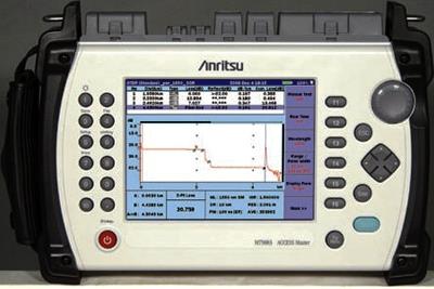
ANRITSU MT9083C1 REPAIR and ANRITSU MT9083C1 CALIBRATION

 
Custom-Cal has a high success rate in the repair of the ANRITSU MT9083C1. A calibration by Custom-Cal is performed by engineers with extensive OEM experience. We have the expertise and the necessary standards to perform the ANRITSU MT9083C1 Calibration, onsite calibration may be available. We specialize in quick turnaround times and we can handle expedited deliveries upon request.

Need another OTDR? Shop for Comparable Products on our   new OTDR page

 
   ANRITSU MT9083C1   Description / Specification:    
ANRITSU MT9083C1 ACCESS Master OTDR Enhanced Display

The Anritsu MT9083C1 ACCESS Master OTDR with full 1 × 64 PON support, up to 42 dB, delivers full featured OTDR performance plus loss test set and quality of service measurement in a surprisingly small and lightweight package. At only 28.4 cm wide × 20 cm tall × 7.7 cm deep and 2.2 kg (4.8 lbs.), it is field portable, yet rugged enough to withstand the outside plant environment. When equipped with power meter, visual light source and IP test options, it replaces several, larger pieces of test equipment. An event dead zone of less than 1 m (80 cm typical) and a sampling resolution of 5 centimeters allow the MT9083B to evaluate connections and troubleshoot central office, FTTx and intra-building faults with ease. In addition to its superb high-resolution performance, the MT9083C1 also features up to 45 dB of dynamic range allowing it to easily test 200 + km spans making it a very useful tool for any network type. Compare current and stored trace data to easily assess changes over time and to locate problems before they effect service or compare traces at different wavelengths to identify installation issues such as macrobending.
Specifications.

Display: 6.5 inch TFT-LCD (640 × 480, with backlight, transparent type) Enhanced display for indoor/outdoor use.
Interface: USB 1.1, Type A × 1 (memory), Type B × 1 (USB mass storage).
Data Storage: Internal memory; 440 MB (up to 1000 traces), External memory (USB); up to 30,000 traces with 512 MB.
Vertical Scale: 0.13, 0.33, 0.65, 1.3, 3.25, 6.5, 13 dB/div.
IOR Setting: 1.400000 to 1.699999 (0.000001 steps).
Units: km, m, kft, ft, mi.
Sampling Resolution: 5 cm (min.).
Reflectance Accuracy: Single mode: ±2 dB, multimode: ±4 dB.
Distance Accuracy: ±1 m ±3 × measurement distance × 10-5 ± marker resolution (excluding IOR uncertainty).
Distance Range: 0.5, 1, 2.5, 5, 10, 25, 50, 100, 200 km (SM), 0.5, 1, 2.5, 5, 10, 25, 50, 100 km (MM).

Options.
053, 1310/1550 nm SM.
057, 1310/1550/1625 nm SM.
010, Protector option (includes rubber bumpers, display cover and shoulder strap).
001, IP Network Connection Check Function.
011, Gigabit Ethernet Upgrade (requires option 001).
004, SMF Optical Power Meter (UPC only).
005, SMF High Power Optical Power Meter (UPC/APC).
007, SMF/MMF Optical Power Meter (UPC/APC).
002, Visible Laser Diode.


Standard Calibration $650.00 *
Click on Logo for More Prices
*This is a Web introductory price for one calibration of the ANRITSU MT9083C1. Price does not in most cases include measurement performance data. Pricing does include NIST traceable calibration and issue of a calibration certificate and calibration label. Pricing may vary slightly due to volume and location of laboratory supporting calibration. Volume pricing may apply. On-site fees may apply depending on logistics, location and volume of work to be completed during the visit.


Related Optical Terms and Definitions. For a complete list go to our  Terms and Definitions Page.

Chirp
A change in the optical frequency caused by direct modulation of the laser. A chirp is a signal in which the frequency increases ('up-chirp') or decreases ('down-chirp') with time. In some sources, the term chirp is used interchangeably with sweep signal.

Isolation
The extent to which optical power from one signal path is prevented from reaching another signal path.

Polarization Extinction Ratio
Polarization Extinction Ratio is the ratio of optical power in the slow axis of the polarization maintaining fiber to optical power in the fast axis within a specified wavelength range.

Sidemode Suppression Ratio
Sidemode Suppression Ratio is the ratio of average signal power to the optical power of the highest sidemode within a distance from 0.1 to 6 GHz to the signal’s optical frequency, expressed in dB.

Wavelength Stability
Wavelength Stability is the change of wavelength during given time span, expressed as ± half the span between the maximum and the minimum of all actual wavelengths.


Please contact us for your ANRITSU MT9083C1 REPAIR and/or ANRITSU MT9083C1 ACCESS Master OTDR Enhanced Display CALIBRATION

I'm interested in: 
Calibration Type (Select one):
Repair Information:
 Serial Number:

 Is there any physical damage?  
 If yes, describe:


What is the description of the problem?

How/when did the problem start?


 (*) Required Fields    For formal quote please fill in all fields.
Company:
From (Email):*
Contact Name:*
Country:*
Address 1:
Address 2:
City:
State/Territory/Province: *
Zip/Postal Code:
Phone:*

Comment: