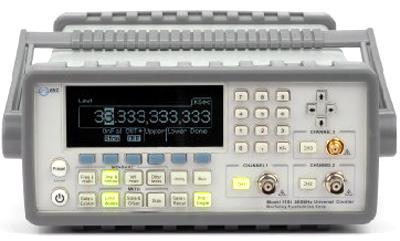
NEW BERKELEY NUCLEONICS CORPORATION 1105 SALES and BERKELEY NUCLEONICS CORPORATION 1105 CALIBRATION

 
Custom-Cal has for sale a new BERKELEY NUCLEONICS CORPORATION 1105. Also, short calibration turn times minimize downtime and reasonable rates decrease your long-term cost of ownership and minimizes downtime of the BERKELEY NUCLEONICS CORPORATION 1105. We specialize in quick turnaround times and we can handle expedited deliveries upon request.

Need another Frequency Counter? Shop for Comparable Products on our   new Frequency Counter page

 
List Price for a new BERKELEY NUCLEONICS CORPORATION 1105, $1,940.00   BERKELEY NUCLEONICS CORPORATION 1105   Description / Specification:   Spec Sheet 
BERKELEY NUCLEONICS CORPORATION 1105 400 MHz Universal Frequency Counter

The Berkeley Nucleonics 1105 400 MHz Universal Frequency Counter has 12 digits of frequency resolution and 40 ps of time interval resolution. The real-time DSP front -end facilitates faster measurement throughput. It includes a RF Channel 3 with a range from 375 MHz to 6GHz and standard Channels 1 & 2 from 1 mHz to 400 MHz. Up to 20 frequently-used setups may be stored in memory.
The 1105 features include Frequency & Ratio (11 digits/sec.) , Time interval , Period (2.5 ns to 1000s) , Duty Cycle, Pulse Width, Rise/Fall Time, Peak Volts (100 Hz~300 MHz) , Phase, Totalize, with a time base temperature stability of < 1 PPM and aging rate of < 2 PPM per year. We can also measure the peak voltage of incoming waveforms as well.
Specifications.

Channel 1 & 2 Input.
DC Coupled: 1 mHz to 400 MHz.
AC Coupled: 200 KHz to 400 MHz (50 Ω), 30 Hz to 400 MHz (1 M Ω).
FM Tolerance: 25%.

Voltage Range and Sensitivity.
1 mH to 225 MHz: 20 mVrms to ±5 V ac + dc (Medium and High), 25 mVrms to ±5 V ac + dc (Low).
225 MHz to 400 MHz: 30 mVrms to ±5 V ac + dc.
400 MHz to 450 MHz: 40 mVrms to ±5 V ac + dc.

Voltage Range and Sensitivity (Single-Shot Pulse).
1.5ns to 10ns Pulse Width: 80 mVpp to 10 Vpp, (150 mVpp with optional rear connectors).
>10 ns Pulse Width: 50 mVpp to 10 Vpp, (150 mVpp with optional rear connectors).

Trigger Level(ATT x 1).
Range: ±5.125 V.
Accuracy: ±(15 mV + 1% of trigger level).
Resolution: 2.5 mV.
ATT x 10: Range X 10.
Trigger Slope: Positive or Negative.

Damage Level.
DC~400 MHz 50 Ω: 12 Vrms.
0 to 3.5 kHz, 1 M Ω: 350 V dc + ac pk.
3.5 kHz to 100 KHz, 1 M Ω: 350 V dc + ac pk linearly derated to 12 Vrms.
100 KHz to 400 MHz, 1 M Ω: 12 Vrms.

Measurement.
Frequency, Period: 1 mHz to 400 MHz (2.5 ns to 1000 s).
Channel 1 and 2 Trigger: Default setting is Auto Trigger at 50%.
Channel 1 and 2 “Auto” Gate Time: 0.1 sec.
STD CH 3: 375 MHz to 6 GHz (0.166 ns to 2.6 ns).
Frequency Ratio: CH 1/ CH 2, CH 1/ CH 3, CH 2/ CH 1, CH 3/ CH1 (Measurement is specified over the full signal range of each input).
Time Interval: Measurement is specified over the full signal ranges of Channels 1 and 2, the width of the pulse must be greater than 1 ns, frequency range to 300 MHz.
Time Interval Results Range: -0.5 ns to 10E+5 s.
Time Interval Resolution: 40 ps.


Standard Calibration $270.00 *
*This is a Web introductory price for one calibration of the BERKELEY NUCLEONICS CORPORATION 1105. Price does not in most cases include measurement performance data. Pricing does include NIST traceable calibration and issue of a calibration certificate and calibration label. Pricing may vary slightly due to volume and location of laboratory supporting calibration. Volume pricing may apply. On-site fees may apply depending on logistics, location and volume of work to be completed during the visit.


Related Bench Equipment Terms and Definitions. For a complete list go to our  Terms and Definitions Page.

dBc
dBc (decibels relative to the carrier) is the power ratio of a signal to a carrier signal, expressed in decibels. If the dBc figure is positive, then the relative signal strength is greater than the carrier signal strength. If the dBc figure is negative, then the relative signal strength is less than carrier signal strength.

Load Regulation
Load regulation is the capability to maintain a constant voltage (or current) level on the output channel of a power supply despite changes in the supply's load (such as a change in resistance value connected across the supply output).

Power Linearity
When changing the power level and measuring the differences (in dB) between actual and displayed power levels, the power linearity is ± half the span (in dB) between the maximum and the minimum value of all differences.

Settling Time
Settling time of an output device is the time elapsed from the application of an ideal instantaneous step input to the time at which the amplifier output has entered and remained within a specified error band, usually symmetrical about the final value.


Please contact us for your new BERKELEY NUCLEONICS CORPORATION 1105 sale price and/or BERKELEY NUCLEONICS CORPORATION 1105 CALIBRATION

I'm interested in: 
Calibration Type (Select one):
Repair Information:
 Serial Number:

 Is there any physical damage?  
 If yes, describe:


What is the description of the problem?

How/when did the problem start?


 (*) Required Fields    For formal quote please fill in all fields.
Company:
From (Email):*
Contact Name:*
Country:*
Address 1:
Address 2:
City:
State/Territory/Province: *
Zip/Postal Code:
Phone:*

Comment: