|
|
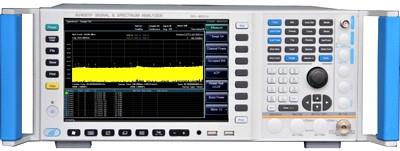
The CeYear AV4051C signal/spectrum analyzer has excellent performance in test dynamic range, phase noise, amplitude accuracy, and test speed. It has various test functions including: high-sensitivity spectrum analysis, power measurement, IQ analysis, transient analysis, pulse parameter analysis, audio frequency analysis, analog demodulation measurement, and phase noise test etc., which can provide you reliable high-performance test service. The AV4051C performance can be further improved by flexible configuration of different options. Through various digital and analog signal output interfaces, the spectrum analyzer can be taken to establish test systems or get secondary development. It can be widely used for signal and equipment test in field of aviation, aerospace, radar detection, communication, electronic countermeasures, and navigation etc.
Specifications.
Frequency range: 3 Hz to 13.2 GHz.
10 MHz Precise Frequency Reference Frequency accuracy: ± (last calibration date x aging rate + temperature stability + calibration accuracy).
Aging rate: ± 1 x 10⁻⁷/year.
Temperature stability: ± 1.5 x 10⁻⁸ (20°C to 30°C) ± 5 x 10⁻⁸ (0°C to 55°C).
Calibration accuracy: ± 5 x 10⁻⁸.
Frequency readout accuracy: ± (frequency readout × frequency reference accuracy + 0.1% frequency band + 5% resolution bandwidth + 2Hz + 0.5 horizontal resolution*)
*: horizontal resolution = span/ (sweep points number - 1).
Frequency counting accuracy: ± (frequency readout x frequency reference accuracy + 0.1Hz.
Span Range: 0Hz (zero span), 10Hz to 13GHz.
Span Accuracy: ± (0.1% x span + span/ (sweep points number - 1).
Sweep time range: 1ms to 4000s (span ≥10Hz), 1us to 6000s (span 0Hz).
Resolution Bandwidth Range: 1Hz to 3MHz (1, 2, 3, 5 stepping) 4, 5, 6, 8, 10MHz.
Resolution Bandwidth Conversion uncertainty: ≤ ± 0.3dB.
Video Bandwidth: 1Hz to 3MHz (1, 2, 3, 5 stepping) 4, 5, 6, 8, 10MHz (rated value).
Signal Analyzing bandwidth: 10Hz to 10MHz (standard), 40MHz (option), and 200MHz (option).
Memory depth: 500MSamples.
Trigger Mode: Free, power source, video, external level (front panel), external level (back panel), burst RF, timer.
Wave-detection Mode: Normal, positive peak, negative peak, sampling, video average power average, voltage average.
SSB phase noise (1GHz carrier, 20°C to 30°C):
Frequency offset 100Hz, -96dBc/Hz, -105dBc/Hz (Typical);
Frequency offset 1 kHz, -115dBc/Hz, -118dBc/Hz (Typical);
Frequency offset 10 kHz, -125dBc/Hz, -129dBc/Hz (Typical);
Frequency offset 100 kHz, -125dBc/Hz, -129dBc/Hz (Typical).
Residual FM (central frequency 1 GHz, resolution bandwidth 10Hz, video bandwidth 10Hz): ≤ (0.25 Hz x N) p-p the rated value within 20ms N is the number of frequency multiple times of LO.
Options.
-H01 Back panel RF input.
-H02 High/intermediate frequency output.
-H03 IF output.
-H04A Reconstruction IF/video signal output.
-H04B Wide band reconstruction IF/video signal output.
-H08 Wide band logarithm wave-detection output.
-H12A 40MHz bandwidth digital interface.
-H12B 200MHz bandwidth digital interface.
-H15 +24V DC power supply.
-H22A AV4711 data recorder.
-H22B AV4712 data recorder.
-H34-13 Low-noise preamplifier.
-H36 Pre-selector bypass.
-H38A 40MHz analyzing bandwidth.
-H38B 200MHz analyzing bandwidth.
-H39 Audio analysis.
-H40 External frequency extension.
-S04 Phase noise test.
-S09 Analog demodulation analysis.
-S10 Transient analysis.
-S13 Pulse signal analysis.
-H98 English options.
-H99 Aluminum transportation case.
|