|
|
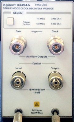
The Agilent 83494A are designed to operate in an Agilent digital communications analyzer. These modules recover clock and data information at standard telecom and datacom rates. The resulting trigger signal is made available to the Agilent mainframe via a connector located on the module’s rear-panel. An external front-panel cable passes the data signal, with some insertion loss, to the receiver module. Channel Type: Single Mode Optical. Clock Recovery Phase Locked Loop Bandwidth: 80 kHz (Internal Path Triggering), 9 MHz (External Output). Data Rates (Mb/s): 155, 622, 2488, 9953. Tracking/Acquisition Range: 155, 622, 2488, ±0.1%; 9953 ±0.03%. Internal Splitter: 10/90. Output Jitter: 155, 622, 2488 0.02 UI RMS; 9953 0.03 UI RMS. Input Power for Clock Recovery: -12 dBm to +3 dBm (155, 622, 2488 Mb/s); -8 dBm to +3 dBm (9953 Mb/s). Input/Output Connectors: FC/PC, 9 /125 um single mode. Auxiliary Recovered Clock and Regenerated Data Outputs: Type N with SMA adapters. Input Return Loss: 28 dB. Input Insertion Loss: 1.5 dB Maximum.
|