|
|
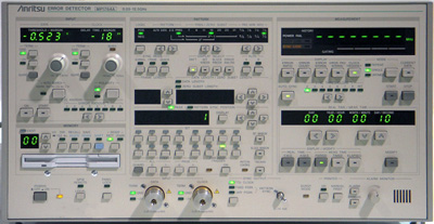
The Anritsu MP1764A Error Detector is used in combination with the MP1763B Pulse Pattern Generator to detect errors used to evaluate conformity with ITU-T standards. In addition, complicated searching for input thresholds or phase adjustments is simplified with the touch of a single key. These functions are ideally suited for the research and development of ultrahigh-speed logic ICs and digital communication systems.
Specifications
Operation frequency: 0.05 to 12.5 GHz.
Data input
Input waveform: NRZ.
Input voltage: 0.25 to 2.0 Vp-p.
Threshold voltage variable range: -3.000 to + 1.875 Vp-p (1 mV steps).
Phase margin: >=70 ps (typical value at 10 Gb/s, PRSS 2^23 - 1, and an input amplitude of 1 Vp-p.
Input sensitivity: 50 mVp-p (typical value at 10 Gb/s and PRBS 2^23 - 1.
Clock input
Input waveform: Rectangular wave «0.5 GHz), rectangular or sine wave (>=0.5 GHz), duty factor, 50%.
Input voltage: 0.25 to 2.0 Vp-p.
Input delay variable range: -500 to +500 ps (1 ps steps).
Receive Pattern
Pseudorandom binary sequence pattern (PRBS);
Pattern: 2^n-1 (n: 7, 9, 11 , 15, 20, 23, 31),
Mark ratio: 1/2, 1/4, 1/8, 0/8 (1/2, 3/4, 7/8, 8/8 are possible with logic inversion).
Number of AND bit shift when setting mark ratio: 1, 3 bits (selectable by using DIP switch on rear panel).
Tracking: Information of pattern set by the error detector is sent to the pulse pattern generator via GPIB.
|