|
|
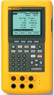
The Fluke 744 Documenting Process Calibrator is a battery powered, hand-held instrument that measures and sources electrical and physical parameters, and provides basic HART communicator functions when used with HART-capable transmitters. It lets you troubleshoot, calibrate, verify, and document your work on process instruments. General features include a thermocouple (TC) input/output jack and internal isothermal block with automatic reference-junction temperature compensation. An analog display to make it easy to read measurements when the input is unstable. The ability to store results for later review.
Specifications.
DC Voltage Measurement.
Input Impedance: 5 MΩ.
Common Mode Error: 0.008% f.s./(Common Mode Volt).
Maximum Input Voltage: 300 V rms.
Range / Resolution / Accuracy, (% of Reading +% of Full Scale (1 year)).
110 mV / 1 μV / 0.025% + 0.015%,
1.1 V / 10 μV / 0.025% + 0.005%,
11 V / 100 μV / 0.025% + 0.005%,
110 V / 1 mV / 0.05% + 0.005%,
300 V / 10 mV / 0.05% + 0.005%.
AC Voltage Measurement.
Ranges : 1.1000 V, 11.000 V, 110.00 V, 300.0 V rms.
Resolution: 11.000 counts in all ranges except 300 V; 3,000 counts on 300 V range.
Input Impedance: 5 M W and <100 pF.
Frequency Range / Accuracy, (% of Reading + Number of Counts (1 year)).
20 Hz to 40 Hz / 2% + 10,
40 Hz to 500 Hz / 0.5% + 5,
500 Hz to 1 kHz / 2% + 10,
1 kHz to 5 kHz / 10% + 20.
DC Current Measurement.
Common Mode Error: 0.01% f.s./(Common Mode Volt).
Maximum Input Voltage: 30 V dc.
Range / Resolution / Accuracy, (% of Reading +% of Full Scale (1 year)).
30 mA / 1 μA / 0.01% + 0.015%,
110 mA / 10 μA / 0.01% + 0.015%.
Resistance Measurement.
Common Mode Error: 0.005% f.s/(Common Mode Volt).
Maximum Input Voltage: 30 V dc.
Range / Resolution / Accuracy, (% of Reading + ohms (1 year)).
11 Ω / 0.001 Ω / 0.05% + 0.05,
110 Ω / 0.01 Ω / 0.05% + 0.05,
1.1 kΩ / 0.1 Ω / 0.05% + 0.5,
11 kΩ / 1 Ω / 0.1% + 10.
Frequency Measurement.
Minimum Amplitude for Frequency Measurement (square wave):
<1 kHz: 300 mV p-p,
1 kHz to 30 kHz: 4 mV p-p,
>30 kHz: 2.8 V p-p.
Maximum input:
<1 kHz: 300 V rms,
>1 kHz: 30 V rms.
Input Impedance: 5 MΩ.
Range / Accuracy, (1 year).
1.00 Hz to 109.99 Hz / 0.05 Hz,
110.0 Hz to 1099.9 Hz / 0.5 Hz,
1.100 kHz to 10.999 kHz / 0.005 kHz,
11.00 kHz to 50.00 kHz / 0.05 kHz.
DC Voltage Output.
Maximum Output Current: 10 mA.
Loading: (0.001% f.s. + 1 μV)/ mA.
Common Mode Error: 0.008% f.s/(Common Mode Volt).
Maximum Input Voltage: 30 V dc.
Range / Resolution / Accuracy, (% of Reading +% of Full Scale (1 year)).
110 mV / 1 μV / 0.01% + 0.005%,
1.1 V / 10 μV / 0.01% + 0.005%,
15 V / 100 μV / 0.01% + 0.005%.
DC Current Output.
Maximum Burden Voltage: 24 V.
Common Mode Error: 0.008% f.s/(Common Mode Volt).
Maximum Input Voltage: 30 V dc.
Range / Mode / Resolution / Accuracy, (% of Output +% of Full Scale (1 year)).
22 mA / Source mA / 1 μA / 0.01% + 0.015%,
22 mA / Simulate Transmitter (Current Sink) / 1 μA / 0.02% + 0.03%.
Resistance Sourcing.
Maximum and Minimum Current through Source Resistance:
11 Ω Range: 8 mA dc max, 0.1 mA dc min;
110 Ω Range: 8 mA dc max, 0.1 mA dc min;
1.1 kΩ Range: 3 mA dc max, 0.01 mA dc min;
11 kΩ Range: 1 mA dc max, 0.01 mA dc min.
Common Mode Error: 0.008% f.s/(Common Mode Volt)
Maximum Input Voltage: 30 V dc
Range / Resolution / Accuracy, (% of Output + ohms (1 year)).
11.000 Ω / 1 mΩ / 0.01% + 0.02,
110.00 Ω / 10 mΩ / 0.01% + 0.04,
1.1000 kΩ / 100 mΩ / 0.02% + 0. 5,
11.000 kΩ / 1 Ω / 0.03% + 5.
Frequency Sourcing.
Waveform Choices: Zero-symmetric sine or positive square wave, 50% duty cycle.
Amplitude: 0.1 to 10 V pk.
Amplitude Accuracy:
0 Hz to 1099 Hz: 3% of output + 0.5% f.s,
1.1 kHz to 10.9 kHz: 10% of output + 0.5% f.s,
11 kHz to 50 kHz: 30% of output + 0.5% f.s.
Maximum Input Voltage: 30 V dc.
Range / Accuracy.
0.00 Hz to 10.99 Hz / 0.01 Hz,
11.00 Hz to 109.99 Hz / 0.01 Hz,
110.0 Hz to 1099.9 Hz / 0.01 Hz,
1.100 kHz to 21.999 kHz / 0.002 kHz,
22.000 kHz to 50.000 kHz / 0.005 kHz.
|