|
|
General description of the
used STANFORD RESEARCH SYSTEMS DG535
for sale.
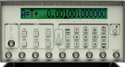
The SRS DG535 Digital Delay and Pulse Generator provides four precisely-timed logic transitions or two independent pulse outputs. The delay resolution on all channels is 5 ps, and the channel-to-channel jitter is typically 50 ps. Front-panel BNC outputs deliver TTL, ECL, NIM or variable level (-3 to +4 V) pulses into 50 O or high impedance loads. The high accuracy, low jitter, and wide delay range make the DG535 ideal for laser timing systems, automated testing, and precision pulse applications. The SRS DG535 has four delay output channels: A, B, C and D. The logic transitions of these outputs can be delayed from an internal or external trigger by up to 1000 seconds in 5 ps increments. The T0 pulse, which marks the beginning of a timing cycle, is generated by the trigger signal. The insertion delay between an external trigger and the T0 pulse is about 85 ns. Specifications. Delays; Channels: Four independent delay outputs : A, B, C and D. Range: 0 to 999.999,999,999,995 seconds. Resolution: 5 ps. Accuracy: 1500 ps + timebase error x delay. Timebase Standard: 25 ppm crystal oscillator. Timebase Optional: 1ppm TCXO (Opt. 03). Timebase External: user provides 10.0 MHz reference. Internal Rate Generator; Rate: Single shot, .001 Hz to 1.000 MHz, or Line. Resolution: 0.001 Hz below 10 Hz, otherwise 4 digits. Accuracy: Same as timebase. Jitter: 1:10,000. Settling: <2 seconds for any rate change. Input External Trigger; Rate: dc to 1/(1 µs + longest delay). Threshold: ±2.56 Vdc. Slope: Trigger on rising or falling edge. Impedance: 1 M-ohm + 40 pF or 50 ohm. Interface: IEEE488 Standard GPIB. Option 06, TTL front panel trigger inhibit input. Option 03, 1ppm TCXO. Option 02, Rear panel T0, A, B, C, D outputs.
|