|
|
General description of the
used ANRITSU MP1758A
for sale.
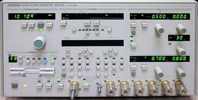
The Anritsu MP1758A Pulse Pattern Generator has a 4·channel data output and a 2-channel clock output. It can generate two patterns: programmable and pseudorandom. The programmable pattern can be up to 128 K bit long for each channel. In addition, seven pseudo-random patterns with periods from 2^7 -1 to 2^31 -1 can be generated with a 1/4 phase difference for each channel. The amplitude and offset voltage of the data/clock output can be set independently for each channel. The setting ranges are 0.5 to 2.0 Vp-p for amplitude, -2.0 to +2.0 VOH for offset voltage, and -500 to +500 ps for delay between the data and clock outputs. The Anritsu MP1758A features; Four independently adjustable output channels. PRBS pattern with max. 2^31-1 bits. Built-in synthesized clock Signal. Specifications. Operation frequency: 0.1 to 12.5 GHz (internal or external clock). External clock Input level: 0.8 to 2.0 Vp-p. External clock Input waveform: sine wave ( >=500 MHz) or square wave. Internal clock Frequency setting resolution: 1 kHz, 1 MHz. Internal clock Reference signal: 10 MHz (internal/external, selectable). Pattern Pseudo-random pattern: 2^n-1 (n=7, 9, 11 , 15,20, 23, 31). Programmable pattern: max. 128 Kbit x 4 channels. Data Output waveform: NRZ. Number of outputs: 4 (CH 1, CH 2, CH 3, CH 4). Amplitude: 0.5 to 2.0 Vp-p (10 mV steps). Offset voltage: -2.0 to +2.0 VOH (5 mV steps). Clock output Number of outputs: 2 (CLOCK 1, CLOCK 2). Amplitude: 0.5 to 2.0 Vp-p (10 mV steps). Offset voltage: -2.0 to +2.0 VOH (5 mV steps). Delay: -500 to +500 ps (1 ps steps). Control interface: GPIB, parallel. Options. -01, CLOCK/CLOCK output. -02, Cross point adjustment.
|