|
|
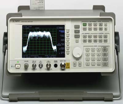
The Agilent 8565EC spectrum analyzer combines outstanding phase noise, sensitivity, 1 Hz resolution bandwidths and wide dynamic range in a Class 3 MIL-rugged package built to withstand harsh environmental conditions. The 8565EC spectrum analyzer offers a complete solution for ACP testing of burst carrier signals using digital modulation such as is used in NADC-TDMA, GSM, DECT, CT2-CAI, PDC and PHS systems. Many of the implementation difficulties of the established standards have been addressed, providing fast, accurate and easy-to-use ACP measurement capability. Another standard feature is the ability to measure from .10 to 99.99 percent occupied bandwidth. Time-gated signal analysis is another standard feature that allows you to easily measure time-varying signals such as pulsed RF, time-division multiple access (TDMA), interleaved and burst-modulated. The 85902A burst carrier trigger can supply a TTL trigger signal. Specifications. Frequency Range (internal mixing): 9 kHz to 50 GHz; 30 Hz to 50 GHz (Option 006), Portable Spectrum Analyzer. Frequency accuracy: ± 1 kHz (CF = 10 GHz). Frequency Span Range: 0 Hz, 100 Hz to maximum frequency. Frequency Readout Accuracy Span >2 MHz x N: ± (freq. readout x freq. ref. accuracy +5% x span +15% x RBW +10 Hz). Frequency Readout Accuracy Span =2 MHz x N: ± (freq. readout x freq. ref. accuracy +1% x span +15% x RBW +10 Hz). Sweep Time Range: Span = 0 Hz: 50 µs to 6,000 s; Span =100 Hz: 50 ms to 100 ks. Resolution bandwidth range: 1 kHz to 2 MHz. Resolution bandwidth Accuracy: 1 Hz to 300 kHz: ±10%; 1 MHz: ±25%; 2 MHz: +50%, -25%. Video Bandwidth Range: 1 Hz to 3 MHz in a 1, 3, 10 sequence. Amplitude Range: Displayed average noise level to +30 dBm. Average noise level (narrowest RBW): -143 dBm. Optimum dynamic range 2nd/3rd order: 117 dB / 100 dB. Amplitude accuracy: ± 3dB. Options; Opt 001: Second IF Output (310.7 MHz). Opt 006: 30 Hz to Freq. Coverage. Opt 008: Signal Identification. Opt 103: Delete Precision Frequency Reference, and 1 Hz and 3 Hz RBWs. Opt 104: Delete Mass Memory Module.
Repair Services / Additional Information.
RF Connector Replacement
Damaged or broken connector (2.4mm) on your microwave signal source or spectrum analyzer? OEM won't sell the replacement to you? Custom-Cal has the solution. Want the connector moved from the from to rear on your signal source, this service is also the solution to undo the obsolete Model # -0041 (RF output connector moved to rear panel)
The input and output connectors on your microwave test equipment affects more than signal fidelity. A damaged connector will destroy expensive adapters and cables.
Whether your RF connector is worn out or was broken through mishandling or accident, Custom-Calibration Solutions will replace the OEM connector with a refurbished connector and new hard-line and bracket, as appropriate. The refurbished connector system will improve:
Signal fidelity (flatness or frequency response)
Input reflection (VSWR)
Output impedance match
Measurement repeatability
Ease of connection
Cable and adapter life
|